If you’re new to electronics, a breadboard can seem like a mysterious block of plastic. You might be wondering, where does the current travel in a breadboard? Understanding this flow is the first step to building amazing circuits. In short, a breadboard guides electricity through specific internal pathways, allowing you to create and test circuits without any soldering.
Understanding the Anatomy of a Breadboard
First, let’s look at the breadboard itself. You will notice hundreds of tiny holes. These holes are your connection points. However, they are not all connected in the same way. Underneath the plastic surface, small metal clips link these holes together in a very organized pattern. Consequently, knowing this pattern is key to making your circuit work.
The Two Main Pathways: Power Rails and Terminal Strips
A standard breadboard has two primary types of connection areas. These are the power rails and the terminal strips. Each serves a distinct purpose in your circuit, and current travels through them differently.
- Power Rails: These are typically found on the sides of the breadboard. They are often marked with red (+) and blue (-) lines. Their job is to distribute power and ground across your entire project.
- Terminal Strips: This is the main central area where you will place your components like LEDs, resistors, and integrated circuits (ICs).
Where Does the Current Travel in a Breadboard’s Terminal Strips?
This is where most of the action happens. The flow of current in the main area is fundamentally different from the power rails. Therefore, it’s crucial to understand the distinction between them.
The Power Rails: Vertical Highways for Electricity
Imagine the power rails as electrical highways. The entire column of holes next to the red line is connected together vertically. Similarly, the entire column next to the blue line is also connected vertically. This design allows you to easily access your positive and negative power source from anywhere on the board. However, the red rail is not connected to the blue rail.
The Terminal Strips: Horizontal Bridges for Components
In contrast, the terminal strips in the middle are connected horizontally. Each row of five holes forms a single electrical connection. For instance, if you plug a component’s leg into the first hole of a row, the other four holes in that same row are now connected to it. A central groove, often called the ravine, separates the two sides of the terminal area. Importantly, the rows do not cross this ravine. This gap is perfect for placing integrated circuits, giving you access to pins on both sides without shorting them.
Tracing the Current’s Journey: A Simple LED Circuit Example
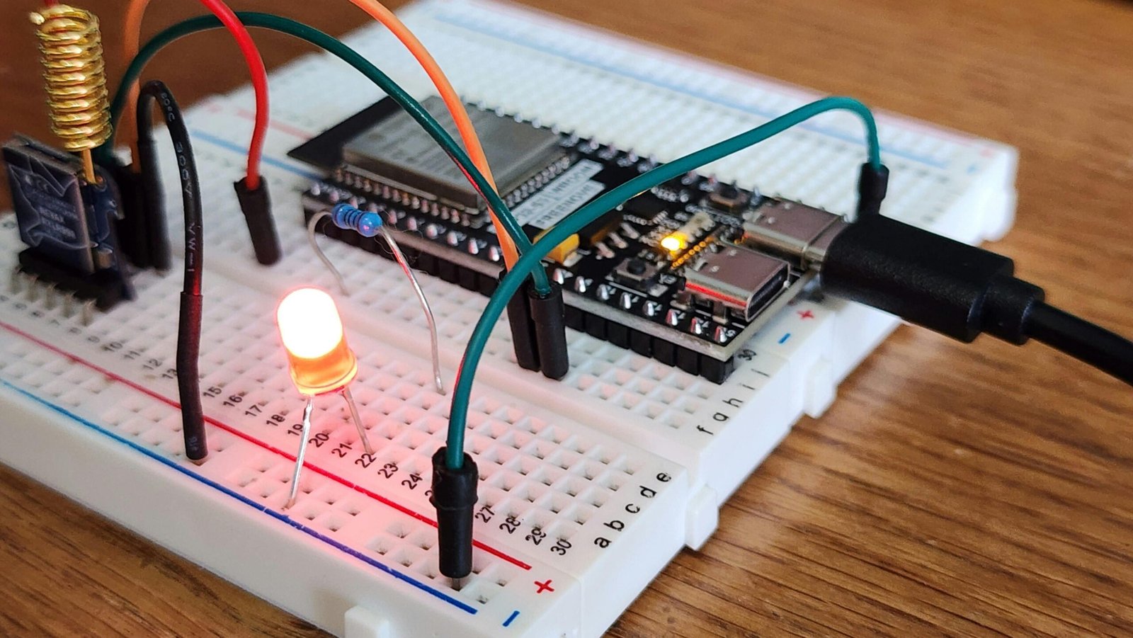
Let’s make this practical. Imagine you want to light up a simple LED. The current must travel in a complete loop from the power source, through the components, and back to the source.
Here is how the current would flow in a typical setup:
- Step 1: First, you connect your power supply to the positive (red) and negative (blue) power rails. Current is now available along these vertical strips.
- Step 2: Next, you run a jumper wire from the positive power rail to a row in the central terminal strip. Current now flows from the rail to all five holes in that specific row.
- Step 3: Then, you place the long leg (anode) of your LED into one of the other holes in that same row. The current travels from the wire, through the metal clip, and into the LED.
- Step 4: You place the short leg (cathode) of the LED into a different row nearby. Now, the current has passed through the LED and is waiting in this new row.
- Step 5: After that, you connect a resistor from the LED cathode’s row to another empty row. This limits the current. The electricity flows through the resistor to this final row.
- Step 6: Finally, you use another jumper wire to connect the resistor’s row back to the negative (blue) power rail. The circuit is now complete, and your LED should light up!
In summary, understanding where the current travels in a breadboard is simple once you grasp the layout. Just remember: power rails connect vertically, and terminal strips connect horizontally. With this knowledge, you are well-equipped to start prototyping your own electronic projects with confidence.